Blog
Cooling techniques and strategies for electronics systems
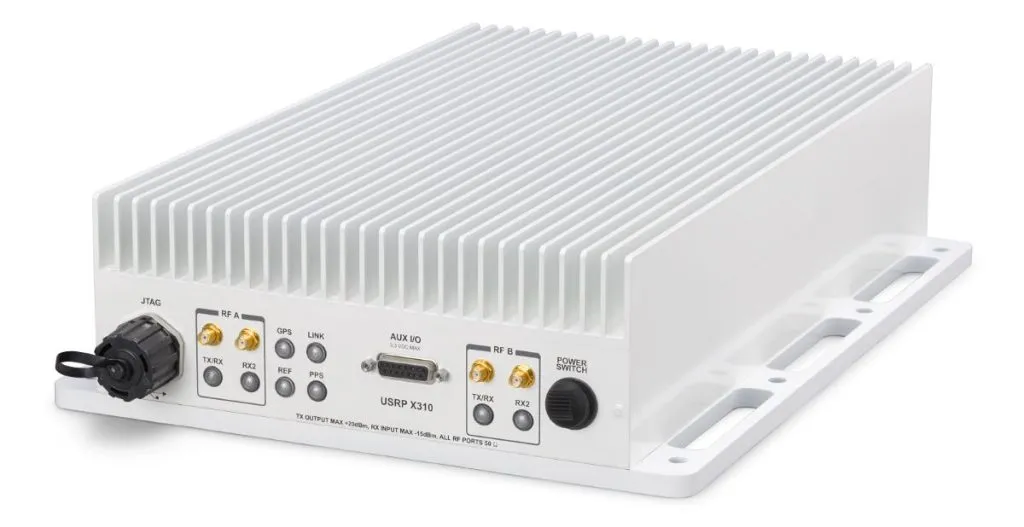
Figure 1: A ruggedised IP67 outdoor software-defined radio with an 60W+ Kintex-7 FPGA and dual 25W daughtercards inside
As computing power gets more advanced the requirements to cool machines becomes more challenging. But particularly with AI systems for advanced computing systems, more complex cooling methods need to be employed. The principles apply across many markets, including telecom, AI, networking, test and measurement, space, satellite and medical.
Modular open systems
For backplane-based designs, especially in defence applications, the modular open systems approach (MOSA) promotes interoperable components and standardised interfaces, allowing systems to be upgraded or reconfigured over time without major redesigns. As a result thermal solutions must work within standardised module formats while managing the heat produced by increasingly dense processors. This open standard approach is also used for AI at the edge. The cooling approach depends largely on the application where the system will be housed.
In a datacentre there is typically more space available and a controlled environment, providing more flexibility in the cooling approach. A forced-air approach is one of the most common and cost effective. Other 19-inch rackmount designs with low to moderate shock/vibration will often utilise forced air cooling.
In environments where there is less control of the environment, that is dust, humidity, or salt-fog, or the electronics may be exposed during servicing, the enclosure system cannot rely solely on open airflow. Instead, it must use a sealed chassis, conduction cooling, or advanced airflow techniques to remove heat from modules and transfer it to the platform structure or controlled airflow channels. An embedded system in an autonomous vehicle, for example, may also face similar challenges and space/power/weight are all limited.
Conduction cooling
OpenVPX is a widely used hardware architecture, which supports MOSA in defence applications. These open standard systems pack high-performance computing modules into a compact chassis, often deployed in aircraft, ground vehicles, or naval systems. These environments place strict limits on available airflow, size, weight and power.
Conduction-cooling provides higher reliability (fans are a significant point-of-failure and may require maintenance, filtering, etc). Therefore, a fanless design utilising conduction-cooling is often employed. These systems utilise heat-sinks, which are basically large chunks of aluminium and/or copper that conduct heat away from the electronics. Often they interface with a finned (see Figure 1) external area, which provides more surface area for the heat to dissipate. The limitation in this approach is there is only so much heat one can dissipate in a fanless system. You can add more metal to the heatsink, but the effective area for cooling the system gets reduced quickly. Lengthening the fins is also a diminishing return. So, as processing power in systems keeps rising, a hybrid approach is often required.
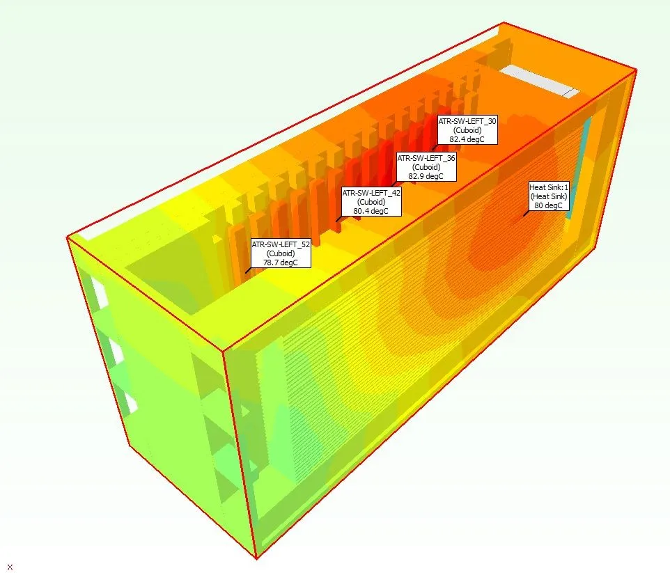
Figure 2: An ATR thermal model shows a MIL rugged chassis for 3U OpenVPX modules simulated to cool 800W in the system
A hybrid cooling approach is increasingly used in embedded systems for air-over-conduction cooling. In this configuration the heat is conducted from components to the module frame or wedge locks conducting the heat to fins or extended surfaces. Then airflow passes across these fins to remove heat. This method combines the reliability of conduction cooling with the improved thermal transfer provided by airflow. Figure 2 shows an air transport rack enclosure for loading multiple OpenVPX boards. The thermal model shows cooling in the airflow-over-fin approach to 800W in the system.
Advanced cooling
While cooling 800W in a 10-slot 3U OpenVPX chassis is a lot, there are many modules in that form factor that are 185W or more. New architectures such as VITA 100 are in development to bring up to eight-times the performance of OpenVPX and again, this means massive amounts of heat to dissipate.
In order to go even further the air flow through (AFT) method is employed in some high-performance systems. Instead of passing air around the outside of modules AFT forces air through the internal structure of the board. There are several sub-specifications for OpenVPX-based systems, including VITA 48.5, VITA 48.9, and VITA 48.8. These combined specifications allow various slot pitches. It’s hard to calculate the exact improvement per inch of pitch, but a 50% thermal dissipation improvement is a reasonable rule of thumb.
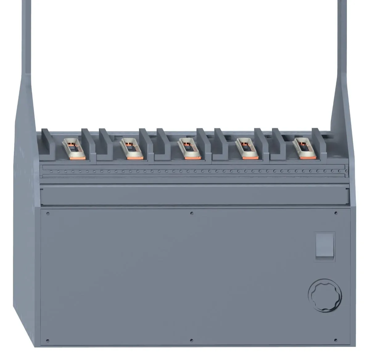
Figure 3: The bottom half of a development enclosure for VITA 48.5 Air Flow Through modules
However, AFT requires carefully designed airflow channels and precise chassis alignment to ensure the airflow paths remain unobstructed. The cooling approach requires new modules and enclosures to be developed. Figure 3 shows an example of a test/development chassis for OpenVPX with AFT card guides for prototyping of high-power boards.
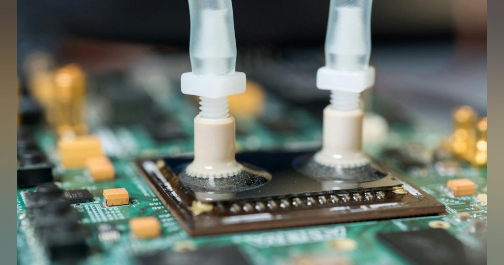
Liquid flow through
The wattage of some systems may need to go beyond what even AFT can provide. Also, not all applications have the luxury of air. As one increases in altitude, the air becomes thinner, so an air-based approach will have limited results. It is not always practical to have enough air ingress/egress in the confines of the space provided for the computing system. There are a few options for Liquid Flow Through (LFT) cooling, including:
- Liquid Flow Through Module – liquid passes through the module as in VITA 48.4
- Liquid Flow Through Sidewall – liquid goes through the sidewall of the chassis, allowing standard VITA 48.2 conduction-cooled modules to be plugged in.
Figure 4 shows an example of LFT card guides for an open frame test/development chassis for VITA 48.4 modules. LFT is especially useful in high-power radar processing, signal processing, or AI acceleration workloads.
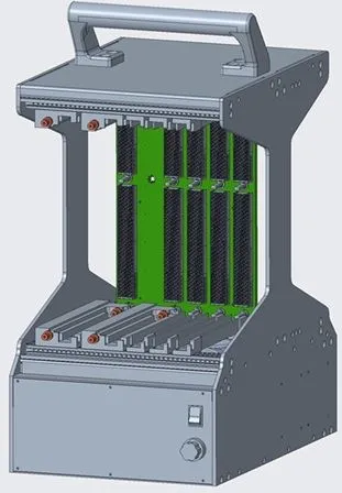
Figure 4: VITA 48.4 is a Liquid Flow Through module specification for OpenVPX modules
However, liquid cooling introduces additional complexity, including pumps, plumbing, seals and maintenance considerations. For this reason LFT is generally used in systems where power density exceeds what air-based cooling methods can handle.
Thermal management is a critical aspect of embedded system design, particularly for rugged MOSA-based architectures. Unlike controlled datacentre environments, military and aerospace systems must handle extreme conditions while maintaining reliable performance.
From forced air and air-over-conduction approaches to advanced techniques such as AFT and LFT, engineers have a range of cooling strategies available. Selecting the right method depends on power density, environmental constraints and system architecture.
See: Innovation in liquid cooling is revolutionising datacentres