Blog
Optimised layer improves chip bead ferrite resistance

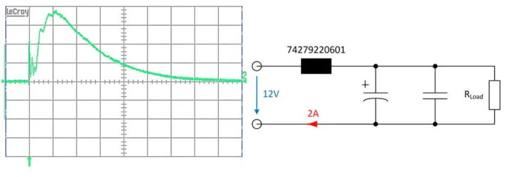
Figure 1: Typical application with peak current at switch-on (5A/DIV |100μs/DIV)
Chip bead ferrites are sensitive to current peaks, which typically occur when switching on power supplies or electric motors. However, an optimised layer design improves their resistance to short-term high current surges.
A chip bead ferrite is an inductor manufactured using a screen-printing process and typically used in EMC filtering. The component consists of a nickel-zinc ferrite and has an inner silver conductor layer a few micrometres thick. This structure makes the classic SMD ferrite susceptible to current peaks above the maximum rated current. These can lead to damage or immediate destruction of the component.
The following therefore applies to SMD ferrites in general, where the maximum rated current in the datasheet also defines the largest permissible current amplitude for short-term loading.
SMD ferrites
With the WE-MPSB component series, however, multilayer ferrites are available, whose datasheets offer a separate peak current consideration. Würth Elektronik has developed an optimised layer design for these products. This is with the aim of achieving high currents, a DC resistance R DC reduced by up to 75% and the highest possible impedance over the entire frequency spectrum.
Figure 1, above, shows a typical application: the multilayer ferrite at the input of the circuit is used as a inline filter. At switch-on, a very high pulse current flows briefly due to the low ESR of the capacitor. This briefly loads the SMD ferrite with a multiple of the specified maximum rated current.
In this example the optimised multilayer ferrite, referred to as a ‘multilayer power suppression bead’ (MPSB), has an impedance of 600Ω with a maximum permissible rated current load of 2.1A. The single current peak in this circuit reaches a value of approximately 19A and it lasts for 0.8ms before it decays to the rated current of the circuit.
For SMD ferrites, the maximum rated current generally defines the maximum current amplitude under short-term load. Multilayer ferrites are available in the WE-MPSB series with pulse load, which considers the peak current in the datasheet.
Test procedure
Current peaks often occur during turn-on of switching power supplies and electric motors. Applications with recurring pulses are intermittent windshield wiper motors in vehicles, or ballasts for lamps. In particular, the input capacitor in a switching regulator often causes a high current peak, which an upstream EMC filter must withstand. In this context pulses are understood to be short-term current peaks with a time limit of less than 8ms until the DC current of the circuit has completely decayed.
A uniform standard for measuring the pulse load capacity of SMD ferrites was found in the definition of the melting integral for fuses. To determine the I²t value of the fuses, a pulse of 8ms is applied to the fuse in accordance with the fuse test process, an interval long enough to heat the fuse. If the fuse holds the current is increased further until the increase leads to the destruction of the fuse. A pause of 10s is required between the pulses to give the component the necessary time to cool.
The rectangular pulse in Figure 2 was selected as the pulse shape for all tests because it loads the component with the highest possible energy during the pulse length, although it will be encountered very rarely at the moment of switch-on.

Figure 2: Possible pulse shapes at the switch-on moment. The square-wave pulse represents the highest load on the component and is therefore in use in the test routine
Empirically measured pulse strength
The datasheet value (Figure 3) is specified as maximum of 24A at 2ms. The calculated I²t value therefore deviates significantly from the measured values. Consequently, it is not possible to use the known calculation of the melting integral I²t applied to a multilayer ferrite.
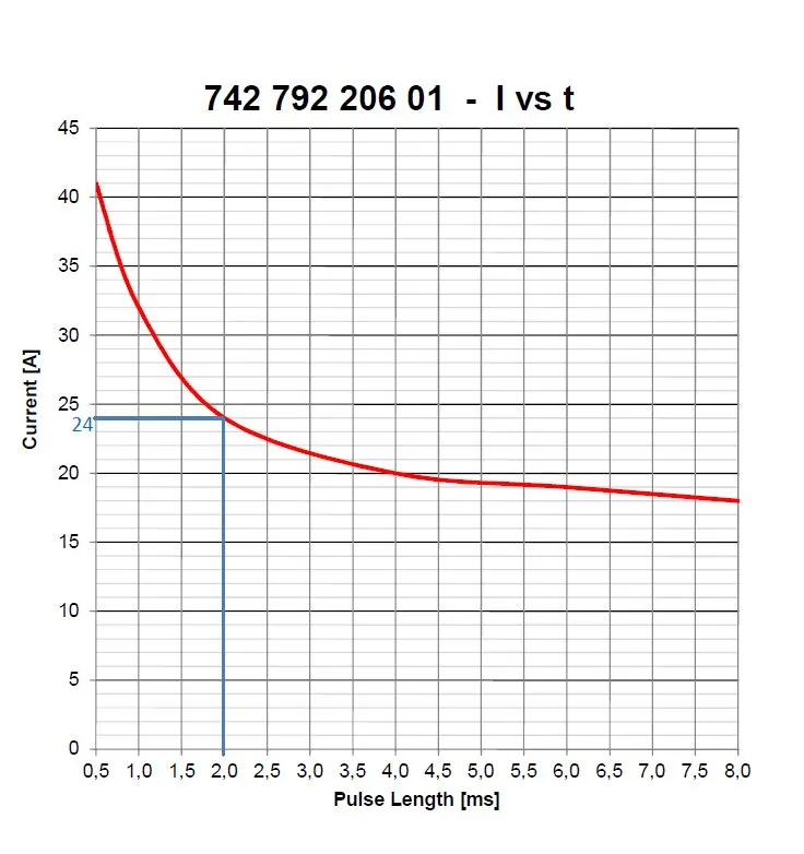
Figure 3: Specified peak current carrying capacity according to datasheet
SMD ferrites are generally not suitable for high pulse currents due to their multilayer structure. An optimised layer design that handles high currents has up to 75% lower R DC and the highest possible impedance across the entire frequency spectrum. Depending on the impedance and current amplitude, the optimum design is used for each individual component.
The current-pulse duration curve shown on the left in Figure 4 shows the maximum permissible peak current for the respective pulse durations tested. The tested range extends from 0.5ms to 8ms.
The maximum permissible pulse current (Figure 4 ) for repetitive pulses is in the second curve. This curve is a limit value consideration of the maximum peak current for repetitive pulses. A maximum pulse length of 8ms was selected to determine the curve.
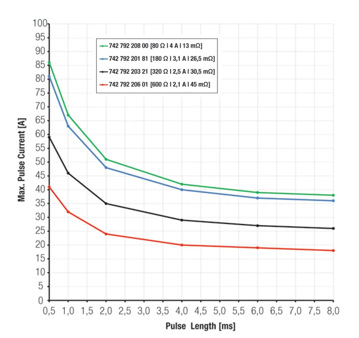
Figure 4: Representation of the current as a function of the pulse duration and the number of pulses at 8ms
Pulse load capacity
The primary factors influencing the pulse load capacity of SMD ferrites are:
- The pulse length t, which undergoes testing from 0.5ms to 8ms as standard. The longer the pulse, the lower the maximum pulse load capacity.
- The number of pulses, which undergoes testing from 10 to 100,000 pulses (Figure 4). As the number of pulses increases, the maximum permissible pulse load capacity decreases.
- The third reducing factor to consider is the temperature: as the temperature rises, the R DC increases, which leads to a further reduction in the maximum pulse load.
Each of these interlinked systems is subject to the dependence of the underlying pause between the individual pulses. To analyse the interlinked system with a shorter pause time, it is necessary to measure the influencing factors temperature [T], pulse repetitions [n] and pulse length [t]. The aim of the WE-MPSB series is to achieve an impedance comparable to that of the WE-CBF series.
WE- MPSB
While the WE-CBF components are usually destroyed if the rated current is exceeded, the WE- MPSB components are designed to withstand higher pulse currents (Figure 5).
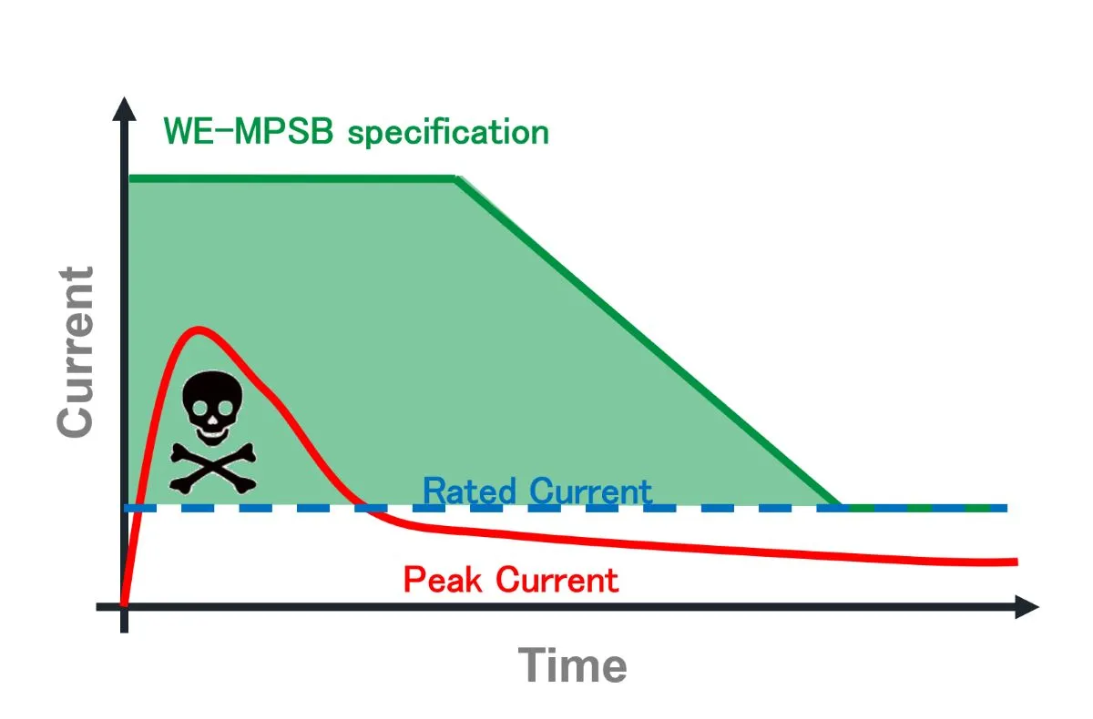
Figure 5: The WE-MPSB series is for a higher pulse current carrying capacity and thus withstands current peaks that occur during the switch-on process
Using the example of the 600Ω types in size 0805 shown in Figure 6, the WE-MPSB series has a higher rated current. This is due to the lower resistance.
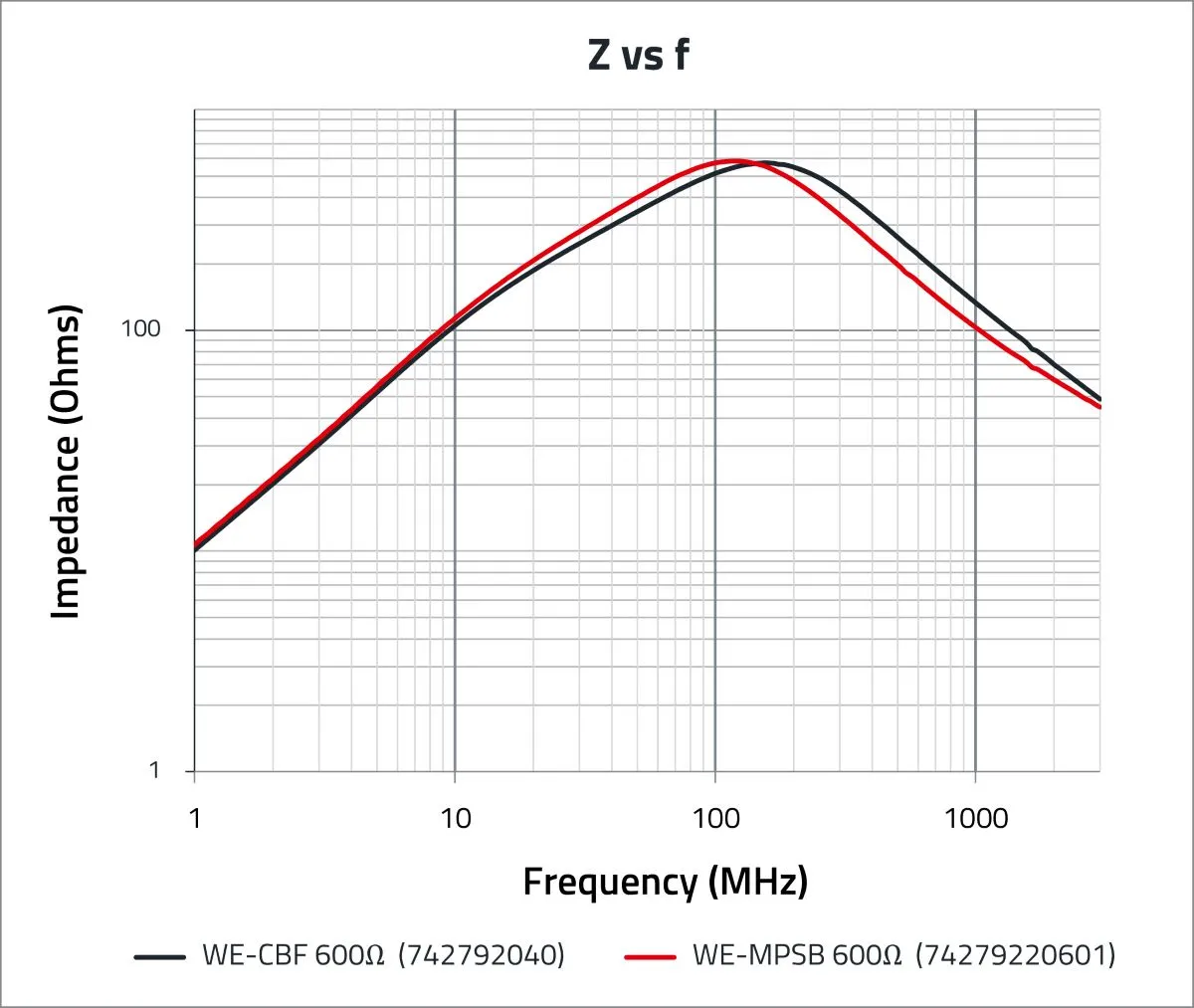
Figure 6: Comparison of the impedance and rated current carrying capacity of the WE-CBF and WE-MPSB 600 Ω type
The WE-MPSB series has a significantly higher pulse load capacity than a comparable component of the WE-CBF series. Figure 7 shows the maximum pulse height of the WE-CBF 600Ω type on the left. And the maximum pulse height of the comparable WE-MPSB 600 Ω type on the right.
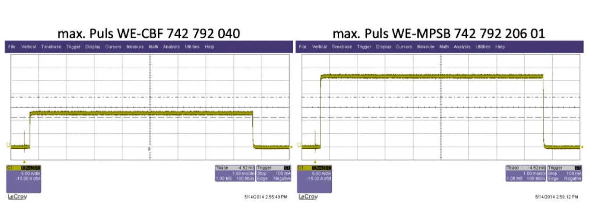
Figure 7: Comparison of the pulse load capacity of the WE-CBF and WE-MPSB series
The WE-MPSB series was developed based on the requirements of circuits that load the multilayer ferrites with short-term peak currents in excess of the rated current. Compared to existing multilayer structures, the layer structure has been optimised to achieve a higher current carrying capacity through lower resistances. This makes the WE-MPSB series particularly suitable for use in circuits with pulse currents.
Wide range of components
For currents above 5A, PCB layouts play an increasingly important role for the current carrying capacity of the conductor tracks. Würth Elektronik is currently working on design tips for this.
See: NIST develops high temperature photonics packaging