Blog
A Blueprint for Inverting Buck-Boost Compensation

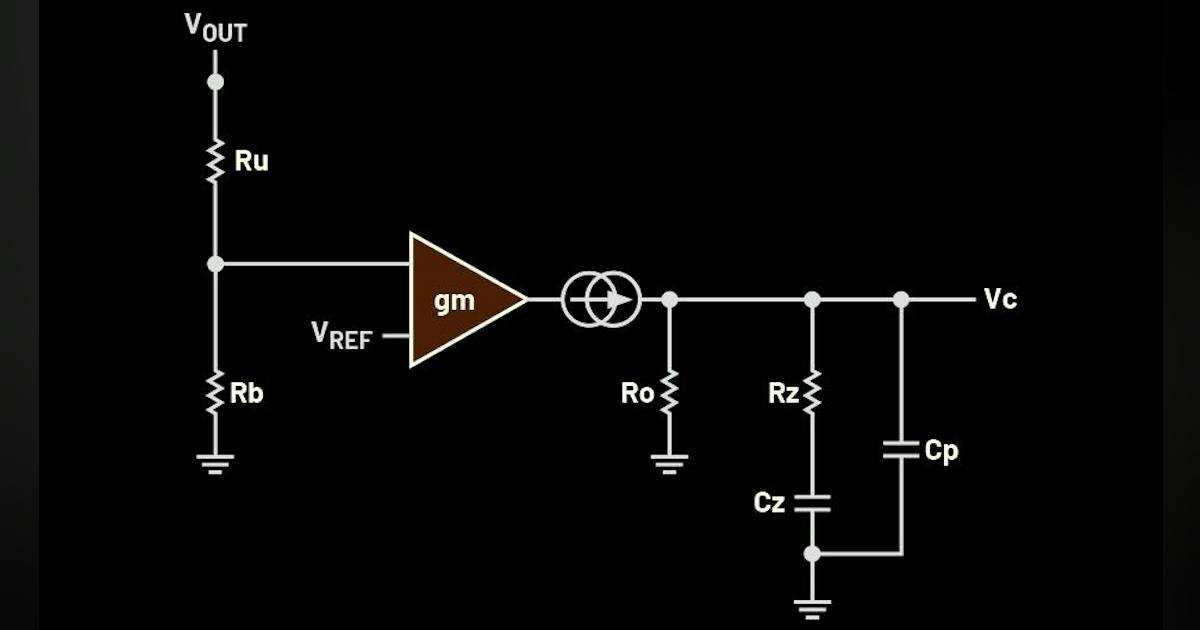
Given all that, it’s evident that the selection of the inductor, L, directly influences the location of the RHP zero and, consequently, limits the maximum achievable crossover frequency of the IBB converter. The choice of output capacitance, COUT, not only determines the output-voltage excursion during load transients, but together with its equivalent series resistance (ESR) and inductor L also shapes the dominant power-stage pole.
These parameters collectively dictate the required loop gain and phase boost during compensator design, ultimately determining the resulting phase margin of the system.
This checklist outlines the essential design requirements:
- High RHP zero for adequate bandwidth (via inductance selection).
- Phase margin (PM) > 45°.
- GM ≥ 10 dB is recommended; however, slightly lower GM may be acceptable when transient performance is prioritized.
- Output voltage deviation ≤ 3% during load transients.
Conclusion
This step-by-step guide gives engineers a systematic approach to compensator design for IBB converters. By deriving the small-signal power-stage model and explicitly accounting for the RHP zero, designers can select an appropriate loop bandwidth and compensation network. The LTspice simulations can be used to confirm that the proposed method achieves stable operation and fast transient response, making it suitable for a wide range of negative-rail-generation applications.
References
Basso, Christophe P. Switch-Mode Power Supplies, Second Edition. McGraw-Hill Professional, February 2008.
Lamp, Erik. “Fast-Transient Negative Voltage Rail for Noise-Sensitive Applications.” Analog Devices, July 2024.
Lamp, Erik and Randyco Prasetyo. “Generating Negative Voltages from a Positive Voltage Supply: Market Requirements and Solutions.” Analog Devices, September 2024.
Mitra, Dipankar. “How to Use the MAX17501 and MAX17502 for Negative Output Voltage Applications.” Analog Devices, April 2014.
Nelson, Carl. “AN19—LT1070 Design Manual.” Linear Technology, June 1986.
Ridley, Raymond B. “A New Small-Signal Model for Current-Mode Control.” Ridley Engineering, 1999.